

Are you preparing to build a new data center or expand your current one? If so, please allow me to introduce you to our data center fiber optic connectivity solution.
1.What is a Data Center Fiber Optic Connectivity Solution?
A Data Center Fiber Optic Connectivity Solution is a comprehensive system of fiber optic cables, fiber optical connectors, patch panels, ODF,transceivers, and strategic design principles. This system creates high-speed, reliable pathways for data transmission within and between data centers, forming their operational backbone.
During the construction of data center facilities, the design of the structured cabling system directly impacts the overall operational reliability. Therefore, ensuring a scientific and standardized approach to cabling design is essential. Based on this, this article introduces the main components of structured cabling in data centers as well as the core products used.

2.Structured Cabling for Data Centers
The structured cabling system in a data center primarily consists of core cabling areas and supporting spaces. The core cabling areas can be further divided into the following components:
- Main Distribution Area (MDA)
This area includes core jumpers and other critical facilities. It is the heart of the structured cabling system, responsible for supporting data communication across one or multiple data center regions.
- Horizontal Distribution Area (HDA)
This area mainly utilizes horizontal jumpers. During the design phase, multiple horizontal cabling paths are arranged within the computer room based on the overall requirements. If the distance between computer equipment and horizontal cabling exceeds standard limits, designers must adjust the HDA layout accordingly to meet the design criteria.
- Zone Distribution Area (ZDA)
In any structured cabling system, the design of connection points is critical. Only with properly designed zone interfaces can various terminal devices be flexibly connected and controlled.
- Equipment Distribution Area (EDA)
This area involves the direct cabling between computer equipment and servers, forming the final link in the structured cabling chain.
3.Core Product Solutions
In a structured data center cabling system, the physical link typically includes: core switch → Main Distribution Area (MDA) → Horizontal/Intermediate Distribution Area (HDA/IDA) → Equipment Distribution Area (EDA) → end devices such as servers and storage. The following products form the key nodes and connecting elements within this link:
3.1 MPO Fiber Patch Panel

Physical Link Position: MDA / HDA / EDA
- Serves as the central management and jumper platform for MPO/MTP trunk fiber cables.
- Installed in standard 19-inch racks to support large-capacity fiber termination and distribution.
- Uses internal MPO adapters to connect with module boxes, decoupling trunks and jumpers physically.
- Supports fast troubleshooting, flexible patching, and quick link adjustment.
3.2 MPO Transition Module Box

Physical Link Position: Transition between MDA → HDA or HDA → EDA
- Converts 12/24-core MPO trunk cables into LC or SC interfaces, connecting to device-side SFP modules.
- Transforms fiber transmission from “parallel” to “serial.”
- Acts as a bridge for upgrading from 10G networks to 40G/100G, seamlessly integrating legacy and high-speed equipment.
3.3 MPO Adapter Panel
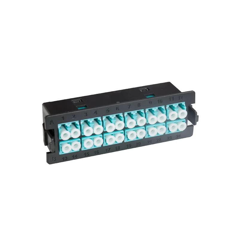
Physical Link Position: Inside patch panels / module connection points
Function:
- Provides multiple MPO adapter ports for connecting MPO jumpers or module boxes.
- Ensures safe and organized high-density cable routing within the patch panel.
- Supports polarity control with compatibility for Type A/B/C configurations to ensure correct link direction.
3.4 MPO Breakout Fiber Cable

Physical Link Position: From HDA / EDA to end devices
- One end is an MPO/MTP connector (for trunk connection), the other end consists of multiple LC or SC connectors (for device connection).
- Used to “fan out” trunk signals, enabling direct connections from switches or patch panels to server ports.
- Ideal for scenarios requiring parallel-to-serial conversion, such as 40G → 4x10G transitions.
3.5 MPO Trunk Fiber Patch Cable
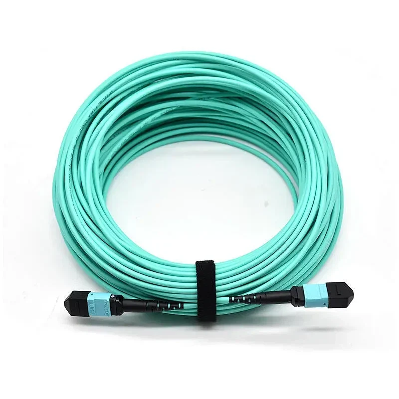
Physical Link Position: MDA ↔ HDA / IDA / EDA (backbone link)
- Establishes high-capacity fiber backbone links between MDA and intermediate or equipment zones.
- Factory pre-terminated with low insertion loss and easy plug-and-play capability.
- Commonly used for interconnecting MPO patch panels or module boxes to support high-speed backbone transmission.
3.6 Uniboot Fiber Patch Cable

Physical Link Position: HDA / EDA ↔ End devices
- Compared to traditional LC jumpers, Uniboot jumpers integrate two fibers into one streamlined structure, reducing space usage.
- Ideal for short-distance connections between high-density panels or servers.
- Improves cable management and airflow within racks.
3.7 40G/100G Active Optical Cable (AOC)

Physical Link Position: Switch ↔ Switch or Switch ↔ Server
- Uses AOC to directly interconnect QSFP+ or QSFP28 ports, enabling high-speed optical transmission.
- Plug-and-play, reducing deployment complexity.
- Especially suitable for high-speed interconnections in Top-of-Rack (ToR) or End-of-Row (EoR) architecture.
4.High-Speed Networking with Optical Transceivers
- 40G Optical Transceiver Modules using MPO interfaces for quick, parallel connections in core and aggregation layers.

- 100G Optical Transceiver Modules designed for high-performance uplinks and next-gen core networks, compatible with MTP/MPO interfaces.

5.Transitioning from 10G to 40G and Beyond
1.Connecting 10G to 40G Networks:
- 4x LC-LC jumpers connect 10G SFP+ ports.
- 1x 12-core MPO jumper connects to a 40G QSFP+ port.
- Managed via high-density patch panels and MPO transition modules.
2.Deploying 400G Infrastructure:
- 400G-DR4 to 4x100G-DR: QSFP-DD connects via 8-core MTP jumpers and MTP-LC modules.
- 400G-SR8 to 2x200G-SR4: Uses MTP-16 to 2×8-core breakout cables and MTP-MTP trunk lines.Managed with modular high-density fiber distribution boxes.
6.Why Choose Our MPO/MTP Solutions?
- Efficiency: Reduce cabling congestion by over 50%
- Speed: Save up to 80% installation time with pre-terminated systems
- Scalability: Easily upgrade to 40G/100G/400G networks
- Performance: Enhanced signal integrity with high-bandwidth OM3/OM4 fibers
7.Looking to upgrade to 40G/100G/400G network architecture—fast?
Discover SoctFiber’s core product solutions for data centers — helping you save procurement time.Strict quality control ensures your business success!