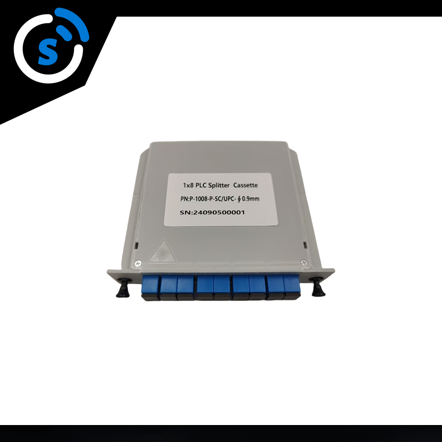
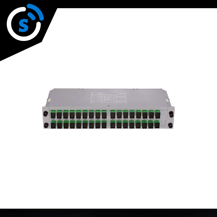
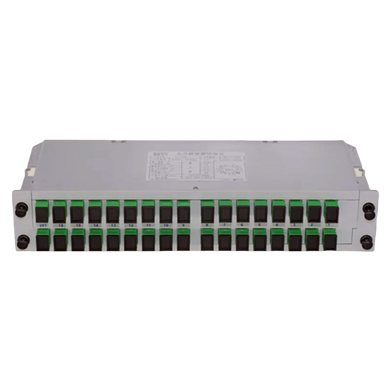

1 x 32 PLC Cassette Fiber Plc Splitter is a planar optical waveguide integrated optical device based on planar optical waveguide technology. It can realize the predetermined distribution of optical power in the wavelength range of 1260nm ~1650nm, which covers the wavelength range of 1310nm, 1490nm and 1550nm used by EPON technology. It is suitable for FTTP optical fiber network system of EPON passive optical network access technology, and is used for broadband and passive optical splitting. Its characteristics are good working wavelength range, good splitting uniformity, low loss, and good device reliability and stability.
Produc name |
Fiber Optic PLC Splitter |
Packaging: |
Carton box |
Delivery Time: |
3-7 working days |
Brand Name: |
SoctFiber |
Place of Origin: |
Jiangsu,China |
Model Number: |
PLC 1X32 |
Connector: |
SC |
OEM: |
Yes |
1.RoHS Compliant
2.Compact Size Design
3.Outstanding Reliability and Stability
4.Minimal Insertion Loss and Low Polarization Dependent Loss (PDL)
5.Broad Operating Wavelength Range: 1260nm to 1650nm
6.Wide Operating Temperature Range: -20°C to 70°C
Port Configuration |
1x2 |
1x3 |
1x4 |
1x6 |
1x8 |
1x12 |
1x16 |
1x32 |
1x64 |
Insertion Loss (dB) |
4.1 |
6.5 |
7.5 |
10.0 |
10.8 |
12.9 |
13.8 |
17.0 |
21.4 |
Loss Uniformity (dB) |
0.6 |
0.6 |
0.6 |
0.6 |
0.8 |
1.0 |
1.2 |
1.5 |
1.5 |
Polarization Dependent Loss(dB) |
0.2 |
0.2 |
0.2 |
0.2 |
0.2 |
0.2 |
0.25 |
0.3 |
0.4 |
Wavelength Dependent Loss(dB) |
0.3 |
0.3 |
0.3 |
0.3 |
0.3 |
0.3 |
0.5 |
0.5 |
0.5 |
Temperature Dependent Loss (dB) |
0.4 |
0.4 |
0.4 |
0.4 |
0.4 |
0.4 |
0.5 |
0.5 |
0.5 |
Return Loss (dB) |
UPC≥50; APC≥55 |
||||||||
Directivity (dB) |
≥55 |
||||||||
Operating Wavelength (nm) |
1260~1650 |
||||||||
Fiber Type |
G657A1 or customer specified |
||||||||
Operating Temperature |
-40~+85 |
||||||||
Storage Temperature |
-40~+85 |
||||||||
1x2;1x3;1x4;1x6;1x8 |
100x25x130mm(WxHxL) |
1x12;1x16 |
100x50x130mm(WxHxL) |
1x32 |
100x102x130mm(WxHxL) |
1x64 |
100x200x130mm(WxHxL) |
Optical attenuation value of the optical splitter = transmitted optical power + additional loss + insertion loss + bare fiber loss.
Formula: ki = Pi / SP * 100%
Pi :The driving power required for each optical link.
SP:The sum of the required driving powers of each optical link carried by the laser.
The PLC Fiber Optical Splitters produced by SoctFiber will indicate the splitting ratio, this depends on the customer's project requirements,such as 1 to 2 is 80%:20% ; 1 to 3 is 70%:15%:15%; 1 to 4 is 70%:10%:10%:10%.
| Item | Parameter | |||||
| Number of Splitter Ports | 1x2 | 1x4 | 1x8 | 1x16 | 1x32 | 1x64 |
| Fiber Type | Single-mode G657A1, as per customer requirements. | |||||
| Operating Wavelength (nm) | 1260~1650 | |||||
| Insertion Loss (dB) | ≤3.9 | ≤7.1 | ≤10.7 | ≤13.8 | ≤17.1 | ≤20.5 |
| Uniformity (dB) | ≤0.4 | ≤0.5 | ≤0.8 | ≤1.0 | ≤1.3 | ≤2.5 |
| Polarization Dependent Loss (dB) | ≤0.2 | ≤0.2 | ≤0.3 | ≤0.3 | ≤0.3 | ≤0.4 |
| Return Loss (dB) | ≥50 | |||||
| Directivity (dB) | ≥55 | |||||
| Operating Temperature | 40℃~+85℃ | |||||
| Storage Temperature | 40℃~+85℃ | |||||
Note: The optical performance of the Fiber Optical Splitters does not include connector loss and adapter loss
| Optical Splitter Type | Typical Insertion Loss Value | Optical Splitter Type | Typical Insertion Loss Value |
| 1x2 | 3.8 | 2x2 | 4.1 |
| 1x4 | 7.2 | 2x4 | 7.5 |
| 1x8 | 10.5 | 2x8 | 10.8 |
| 1x16 | 13.8 | 2x16 | 14.1 |
| 1x32 | 17.1 | 2x32 | 17.4 |
| 1x64 | 20.1 | 2x64 | 20.4 |
| 1x128 | 23.7 | 2x128 | 24.0 |
In practical operations, additional loss values can be measured and assessed as needed. It only needs to detect and record the value according to certain operating specifications, and classify different links.
The loss of a general 1×N single-mode standard splitter is as follows:
| Number of Splitter Ports | 2 | 3 | 4 | 5 | 6 | 7 | 8 | 9 | 10 | 11 | 12 | 16 |
| Additional loss (dB) | 0.2 | 0.3 | 0.4 | 0.45 | 0.5 | 0.55 | 0.6 | 0.7 | 0.8 | 0.8 | 1 | 1.2 |
Formula: IL=-10lg(Po/Pi)
Po: the optical power at the output end.
Pi: the optical power at the input end.
Note: In the formula, Po/Pi is equivalent to the splitting ratio of the splitter, that is: IL=-10lg(ki). For example, there is a one-to-two splitter, which is a 28 split, that is, the splitting ratio is 20%:80%. The theoretical insertion loss of its 20% split link is -10lg(20%), which is approximately equal to 6.99dB.
| Types of Losses | Quantity | Average Loss | Primary Splitter Scenario | Secondary Splitter Scenario | ||||||
| 1:64 | 1:32 | 1:64 | 1:32 | |||||||
| Fiber Optical Cable(KM) | 4 | 0.35 | 1.4 | 1.4 | 1.4 | 1.4 | 1.4 | 1.4 | 1.4 | 1.4 |
| Live Connector (Units) | 6 | 0.5 | 3 | 3 | 3 | 3 | 3 | 3 | 3 | 3 |
| Primary Splitter | 1:64 | 19.7 | 19.7 | |||||||
| 1:32 | 16.5 | 16.5 | ||||||||
| 1:16 | 13.5 | 13.5 | ||||||||
| 1:8 | 10.5 | 10.5 | 10.5 | |||||||
| 1:4 | 7.2 | 7.2 | 7.2 | |||||||
| 1:2 | 3.2 | 3.2 | ||||||||
| Average Attenuation Total (dB) | 24.10 | 20.9 | 17.9 | 14.9 | 11.6 | 14.9 | 11.6 | 7.6 | ||
| Primary Splitter Output Power (dBm) | Margin 1dB | -23.10 | -19.90 | -16.90 | -13.90 | -1.67 | -13.90 | -10.60 | -6.60 | |
| Types of Losses | Quantity | Average Loss | Secondary Splitter Scenario | |||||
| 1:64 | 1:32 | |||||||
| Fiber Optical Cable(KM) | 0.5 | 0.35 | 0.175 | 0.175 | 0.175 | 0.175 | 0.175 | 0.175 |
| Live Connector (Units) | 2 | 0.5 | 1 | 1 | 1 | 1 | 1 | 1 |
| Secondary Splitter | 1:64 | 19.7 | ||||||
| 1:32 | 16.5 | |||||||
| 1:16 | 13.5 | 13.5 | 13.5 | |||||
| 1:8 | 10.5 | 10.5 | 10.5 | |||||
| 1:4 | 7.2 | 7.2 | 7.2 | |||||
| 1:2 | 3.2 | |||||||
| Average Attenuation Total (dB) | 8.38 | 11.68 | 14.68 | 8.38 | 11.68 | 14.68 | ||
| Secondary Splitter Output Power (dBm) | Margin 1dB | -25.28 | -25.28 | -25.28 | -22.28 | -22.28 | -22.28 | |
In practical operation, manual calculation of this value is unnecessary, as a defined reference standard is available. By adhering strictly to the numerical standard, loss values at different wavelengths can be measured to determine the final loss value.
When the optical signal is transmitted through the optical splitter, its loss value has nothing to do with the transmission direction. Whether the optical signal is transmitted from the input end of the optical splitter to the output end, or from the output end to the input end, the loss value is the same in both transmission directions. Therefore, we only need to measure the loss value of the optical splitter in one direction.
| Wavelengths | Fiber Attenuation Coefficient (Reference Value) |
| 1310nm | 0.3~0.4dB/km |
| 1550nm | 0.15~0.25dB/km |
| 850nm | 3.75dB/km |
From start to finish, we ensure quality and care —smooth production, safe delivery!